
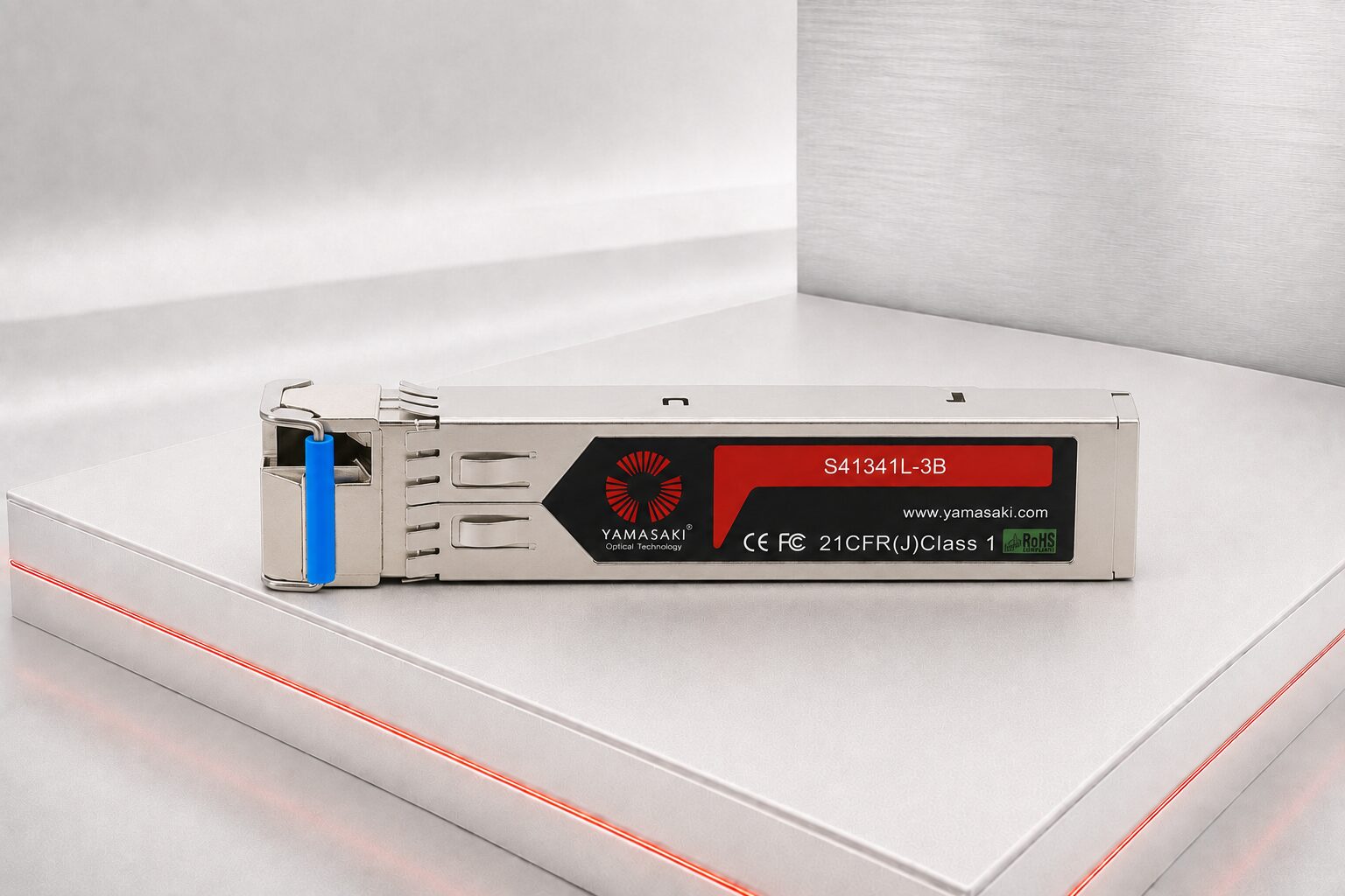
The Yamasaki 1G BiDi SFP Transceiver delivers full-duplex Gigabit Ethernet connectivity over a single optical fibre. Available in models supporting transmission distances from 3 km to 80 km, these compact, lightweight and hot-pluggable transceivers help increase the capacity of compatible singlemode fibre networks. Complementary wavelength pairs and equipment-specific programming options are available to suit a wide range of network applications.
| File | File size |
|---|---|
| 1G Bi-Directional SFP | 672 KB |
A 1G BiDi SFP Transceiver provides full-duplex Gigabit Ethernet communication over a single optical fibre, helping organisations increase the capacity of existing singlemode fibre infrastructure. Instead of using one fibre for transmission and another for reception, BiDi technology carries both directions of communication over the same fibre by using two different optical wavelengths.
The Yamasaki 1G BiDi SFP range combines compact SFP packaging, hot-pluggable installation, Digital Optical Monitoring and broad equipment compatibility. Consequently, these transceivers provide a practical solution for enterprise networks, telecommunications infrastructure, campuses, industrial facilities, CCTV systems and other applications where fibre availability matters.
However, selecting a BiDi transceiver requires more than choosing a transmission distance. Network designers must also consider complementary wavelengths, optical link budget, connector type, fibre condition, host-equipment compatibility and the specifications of the transceiver installed at the opposite end.
This Knowledge Centre explains how 1G BiDi technology works, where it provides the greatest value and how to select the correct matched transceiver pair.
A 1G BiDi SFP Transceiver is a compact optical module that transmits and receives Gigabit Ethernet signals through one singlemode optical fibre.
BiDi is an abbreviation of bidirectional. You may also see the technology described as Bi-Directional, WDM SFP or single-fibre SFP. Although the terminology varies, each description refers to the same fundamental principle: transmitting and receiving optical signals over one fibre by assigning a different wavelength to each direction.
A conventional duplex optical connection typically uses:
In contrast, a BiDi optical connection typically uses:
Therefore, BiDi transceivers can reduce the number of fibre cores required for a connection without reducing the link’s full-duplex communication capability.
A BiDi SFP contains an optical transmitter, an optical receiver and a wavelength-selective optical component that combines and separates the two optical signals.
The transmitter converts electrical network data into an optical signal at a specified wavelength. Meanwhile, the receiver detects incoming light at a different wavelength and converts it back into an electrical signal for the connected switch, router or media converter.
For example, one transceiver might:
The complementary transceiver at the opposite end would then:
Because the transmit wavelength at each end matches the receive wavelength at the other end, both devices can communicate simultaneously through the same fibre.
This process uses wavelength division multiplexing principles. However, the wavelength combining and separation occur within the transceivers, so the link does not generally require an external WDM device.
One of the most important requirements of any BiDi link is the use of complementary transceivers.
Unlike many conventional duplex SFP modules, two identical BiDi modules will not normally form a working link. If both modules transmit and receive on the same wavelengths, the transmitter at one end will not align with the receiver at the other.
Instead, the pair must have reversed wavelength specifications.
| Link end | Transmit wavelength | Receive wavelength |
|---|---|---|
| End A | Wavelength 1 | Wavelength 2 |
| End B | Wavelength 2 | Wavelength 1 |
In addition, both modules should support a compatible data rate, transmission distance, optical budget and Ethernet standard.
Therefore, network operators should identify BiDi transceivers as complete link pairs rather than selecting each module independently. Clear labelling at both ends also helps prevent confusion during installation and future maintenance.
The primary benefit is the ability to establish a full-duplex Gigabit Ethernet link over one optical fibre. As a result, organisations can conserve fibre cores for future services or additional network connections.
Where a cable contains limited spare fibres, replacing duplex links with BiDi links may allow the infrastructure to support more connections.
For example, two available fibres can potentially support two separate BiDi links instead of one conventional duplex link. However, each link still requires its own correctly matched transceiver pair.
Installing additional fibre can involve cable pathways, trenching, civil works, building access, traffic management or production interruptions. Therefore, using existing fibre more efficiently may reduce the need for costly infrastructure expansion.
When a suitable singlemode fibre is already available, BiDi technology may allow technicians to activate a new connection without waiting for another cable to be installed.
Even where additional fibres remain available, conserving them provides resilience and flexibility. Spare fibres may support future services, temporary connections or restoration after fibre damage.
Remote equipment cabinets, CCTV installations, industrial sites and telecommunications facilities sometimes have only one usable fibre available. A BiDi link can provide full-duplex Ethernet connectivity in these situations, provided the fibre and optical budget meet the module requirements.
Yamasaki 1G BiDi SFP Transceivers use a hot-pluggable SFP form factor. Therefore, a technician can generally install or replace the module without powering down the host switch, router or media converter.
This capability can reduce service disruption during:
Nevertheless, hot-pluggable does not mean that every removal or installation will be operationally risk-free. Disconnecting a live network link will still interrupt traffic passing through that link. Furthermore, technicians should follow the host-equipment manufacturer’s instructions, observe laser-safety requirements and protect optical connectors from contamination.
Digital Optical Monitoring, also known as DOM or Digital Diagnostic Monitoring, allows compatible network equipment to read operating information from the installed transceiver.
Depending on the module and host platform, monitored parameters may include:
These values give technicians greater visibility into the condition of the optical connection.
For example, low received optical power could indicate excessive fibre attenuation, dirty connectors, damaged patch leads, poor splices or an incorrect transceiver pair. Meanwhile, unusually high temperature or abnormal supply voltage may point to an equipment or environmental issue.
However, DOM readings should support proper optical testing rather than replace it. A transceiver reports the conditions it sees at that moment, while calibrated test equipment provides more detailed information about channel loss, events and fibre condition.
Every optical transceiver has a limited range of optical power within which it can operate reliably.
The transmitter launches light into the fibre. As the signal travels through the channel, it experiences losses from:
The receiver must still receive enough optical power to detect the signal correctly. Therefore, the total channel loss must remain within the transceiver’s available optical link budget.
A simplified link-budget calculation is:
Available link budget = minimum transmitter output minus receiver sensitivity
The anticipated channel loss should include all known losses plus a reasonable engineering margin. This margin allows for ageing, repairs, additional connections, measurement uncertainty and future deterioration.
Selecting a longer-distance transceiver does not automatically improve every link. On a very short channel, a high-power optical transmitter may overload the receiver unless the module can accommodate the received power or an appropriate optical attenuator is used.
Accordingly, the correct transceiver should suit both the physical distance and the calculated optical performance of the channel.
Yamasaki 1G BiDi SFP Transceivers are intended for compatible singlemode fibre applications. The specific module datasheet should confirm the required fibre type, wavelength pair, connector interface and supported reach.
BiDi SFP modules commonly use a simplex LC connection because only one fibre is required. Therefore, the installed fibre patch lead must match the transceiver’s connector type and the connector interface presented by the optical distribution equipment.
Before connecting the transceiver, technicians should:
Connector cleanliness is particularly important. Even a small amount of dust, oil or debris can increase insertion loss, cause signal instability or damage an optical interface.
Yamasaki 1G BiDi SFP Transceivers support many commonly used switches, routers, media converters and network access devices.
However, not every SFP port accepts every third-party transceiver. Some equipment manufacturers use vendor-specific coding, identification data or software controls. As a result, a physically compatible transceiver may generate an unsupported-module warning or may not operate correctly in a particular device.
Anderson Corporation can provide compatibility programming for selected equipment platforms. To identify the correct version, provide:
Compatibility should be confirmed at both ends of the link because different equipment brands may be installed at each location.
First, verify that the network port supports a 1G SFP interface. A physically similar SFP module does not guarantee compatibility with ports designed for different speeds or interface standards.
Determine the complete optical path length rather than relying only on the straight-line distance between buildings or cabinets.
Include fibre attenuation, connectors, splices and any other passive losses. Then add an appropriate engineering allowance.
Confirm the transmit and receive wavelengths required at both ends. The modules must form a complementary pair.
Verify that the installed channel uses compatible singlemode fibre and that the transceiver connector matches the fibre interface.
Identify the switch, router or media converter at each end. Where necessary, request suitable compatibility coding.
If optical monitoring is important, verify that both the transceiver and the network equipment support the required DOM functions.
Review the expected temperature, enclosure ventilation, power conditions and environmental exposure. For industrial or outdoor cabinets, confirm whether a commercial or industrial temperature range is required.
BiDi SFPs can connect communications rooms, floors and buildings while reducing the number of fibres consumed by each Gigabit Ethernet connection.
Schools, universities, hospitals and corporate campuses often operate fibre links between multiple buildings. Where spare fibre capacity is limited, BiDi technology can support additional services without immediately installing another backbone cable.
Telecommunications providers can use single-fibre transceivers in access and aggregation networks where efficient use of fibre infrastructure is commercially and operationally important.
Factories, utilities, mines, transport facilities and process-control environments may need Ethernet connectivity across long distances. BiDi modules can support compatible industrial switches and media converters where only one singlemode fibre is available.
Distributed surveillance networks frequently connect remote camera cabinets, recording systems and control rooms. A BiDi optical link can provide Gigabit Ethernet connectivity while preserving fibres for other security or operational services.
BiDi transceivers can connect separate buildings through existing underground, aerial or campus fibre infrastructure. Fibre also provides electrical isolation between buildings, although the complete installation must still follow relevant network design and safety practices.
Before installation, record the part number, transmit wavelength, receive wavelength and designated location of each module. This simple process reduces the risk of placing two non-complementary transceivers on the same link.
During commissioning:
If the link does not establish, confirm the wavelength pairing before replacing equipment. Incorrect pairing remains one of the most common causes of BiDi commissioning problems.
If a link fails or becomes unstable, investigate the system methodically.
Check that the modules form a complementary pair, the fibre connects the correct locations and both devices support the transceivers.
Confirm the equipment model and compatibility coding. Also check that the SFP is fully seated in the port.
Inspect and clean all connector interfaces. Then review channel loss, fibre bends, splice quality and the specified transmission distance.
A short link combined with a high-output transceiver may deliver more power than the receiver accepts. Compare the DOM reading with the receiver’s maximum input specification.
Investigate contaminated connectors, damaged patch leads, excessive channel loss, temperature changes, loose modules and equipment configuration.
Because both directions use different wavelengths, a fault may affect one direction more than the other. Check the transmit and receive power at both ends, then verify the wavelength specifications of the installed pair.
Choosing the correct 1G BiDi SFP Transceiver involves far more than matching an advertised transmission distance. Instead, a dependable bidirectional optical link requires an understanding of complementary wavelengths, singlemode fibre, connector interfaces, optical link budgets and host-equipment compatibility.
That is why Anderson Corporation continues to develop one of Australia’s most comprehensive Knowledge Centres dedicated to 1G BiDi SFP transceivers and supporting single-fibre network infrastructure.
Whether you need to conserve fibres within an existing backbone, connect buildings across a campus or extend an industrial communications network, our technical articles will help you make informed product-selection and deployment decisions.
The Yamasaki 1G BiDi SFP range supports Gigabit Ethernet communication over one singlemode optical fibre. Available models provide transmission distances from 3 kilometres to 80 kilometres, subject to the installed fibre channel and available optical link budget.
Unlike conventional duplex SFP transceivers, BiDi modules must operate as complementary wavelength pairs. Therefore, successful selection requires careful consideration of the transceiver installed at each end of the link.
As this Knowledge Centre continues to grow, you will find practical guidance covering every stage of selecting, specifying, installing, commissioning, troubleshooting and managing 1G BiDi optical links.
If you are new to bidirectional optical networking, these educational guides will explain the fundamental principles behind 1G BiDi SFP technology.
For example, you will learn how a BiDi SFP transmits and receives data simultaneously through one optical fibre. The guides will also explain how wavelength division multiplexing allows the module to separate the incoming and outgoing optical signals.
In addition, the educational series will examine the relationship between the transceiver, host equipment, simplex patch lead and installed singlemode fibre channel. Readers will therefore gain the foundational knowledge required before comparing individual BiDi models.
The guides will also explain the difference between the customer-facing Gigabit Ethernet service and the underlying optical signalling rate. Moreover, they will examine why a 1G network interface commonly operates at an optical line rate of up to 1.25 Gbit/s.
Most importantly, readers will learn why two identical BiDi modules do not generally create a functioning optical link. Instead, each link requires two complementary modules with reversed transmit and receive wavelengths.
Wavelength pairing is one of the most important aspects of selecting a 1G BiDi SFP Transceiver.
Each module transmits at one wavelength and receives at another. Therefore, the module installed at the opposite end must transmit on the first module’s receive wavelength and receive on its transmit wavelength.
For example, one end of a link may transmit at 1310 nm and receive at 1550 nm. The complementary module must then transmit at 1550 nm and receive at 1310 nm.
However, wavelength pairing involves more than matching two numbers. The modules must also support compatible data rates, optical budgets, transmission distances, connector interfaces and network standards.
Our wavelength-pairing guides will explain:
Accordingly, these guides will help installers, network designers and procurement teams avoid one of the most common BiDi selection errors.
Once you understand the fundamental principles, you can explore the engineering factors that determine whether a 1G BiDi SFP Transceiver will operate successfully across a particular optical channel.
Our technical guides will examine transmitter output, receiver sensitivity, receiver overload, optical attenuation, wavelength selection and Digital Diagnostic Monitoring.
They will also explain how fibre attenuation, connectors, adaptors, fusion splices, patch leads and other passive components contribute to the total channel loss.
Therefore, network designers will be able to assess the complete optical path instead of relying solely on a module’s advertised maximum transmission distance.
Furthermore, the technical series will examine why both directions of a BiDi link require assessment. Because the two directions use different wavelengths and separate transmitters and receivers, the available optical budget may not be identical in each direction.
These guides will also distinguish between minimum received power, receiver sensitivity and maximum permitted received power. That distinction becomes particularly important when specifying extended-reach modules for short or unusually low-loss connections.
Articles Coming Soon
BiDi and conventional duplex SFP transceivers may use the same physical SFP form factor. However, they use fundamentally different optical connection architectures.
A conventional duplex transceiver generally uses:
By comparison, a BiDi transceiver generally uses:
Our comparison guides will explain the advantages, limitations and appropriate applications of each architecture.
For example, a conventional duplex connection may provide a straightforward solution where adequate fibre cores remain available. Conversely, a BiDi connection may provide greater value where spare fibre capacity is limited or installing another cable would prove expensive and disruptive.
The comparison series will also examine BiDi SFPs alongside the Yamasaki conventional 1G SFP Transceiver and copper 1G RJ45 SFP Transceiver. Consequently, readers can compare single-fibre optical, duplex-fibre optical and copper Ethernet connectivity.
Articles Coming Soon
A 1G BiDi SFP Transceiver allows a full-duplex Gigabit Ethernet connection to operate over one compatible singlemode fibre.
Therefore, BiDi technology can help organisations increase the number of connections supported by existing fibre infrastructure. For example, two fibres previously required for one conventional duplex link may potentially support two independent BiDi links.
However, network designers must still assess the complete infrastructure before converting existing connections.
The planning process should identify:
Our single-fibre network-planning guides will examine how BiDi technology can help organisations conserve fibre cores, extend existing infrastructure and plan additional network services.
The guides will also explain why BiDi transceivers increase fibre utilisation rather than the data rate of an individual 1G connection. A 1G BiDi link still provides Gigabit Ethernet; it simply achieves that connection through one fibre instead of two.
Articles Coming Soon
A 1G BiDi SFP Transceiver must match the installed fibre type, optical channel and complete routed distance.
Yamasaki 1G BiDi SFP models support compatible singlemode fibre connections across distances ranging from 3 kilometres to 80 kilometres, depending on the selected model.
Nevertheless, the advertised reach represents a design classification rather than a guarantee that every channel of that length will operate successfully.
The achievable distance depends on several factors, including:
Furthermore, the installed fibre route may travel considerably further than the straight-line distance between the network endpoints. For example, a campus cable may pass through communications rooms, risers, service pathways, underground pits and maintenance loops before reaching the destination.
Therefore, network designers should use the complete installed route length and calculated channel loss when selecting a transceiver.
Our fibre and distance guides will explain how these variables affect practical 1G BiDi SFP selection.
Articles Coming Soon
An optical link budget determines whether enough optical power will reach the receiver after the signal passes through the complete fibre channel.
To calculate the available link budget, designers compare the transmitter’s minimum output power with the receiver’s sensitivity. They must then compare that available budget with the anticipated channel loss.
Channel-loss calculations should include:
However, each direction of a BiDi connection should be assessed separately. The transmit characteristics at one end may differ from those at the other, while the fibre’s attenuation also varies according to wavelength.
Our optical link-budget guides will explain how to calculate anticipated losses, interpret transceiver specifications and retain an appropriate operating margin.
In addition, the guides will examine receiver overload. A long-distance transceiver installed across a short, low-loss channel may deliver more optical power than the receiver can safely accommodate. Therefore, selecting the longest available transmission distance does not necessarily produce the most reliable design.
Where necessary, a suitable optical attenuator may reduce received power. However, designers should calculate and verify the requirement rather than adding attenuation without supporting measurements.
Articles Coming Soon
Before purchasing a 1G BiDi SFP Transceiver, organisations must confirm both the optical-channel requirements and the host-equipment requirements.
The procurement process should identify:
In addition, a purchase request should identify the two modules as a complementary pair. Ordering one module without confirming the transceiver at the opposite end can result in incompatible wavelength specifications.
Where an existing module requires replacement, the customer should provide its manufacturer, product code, transmit wavelength, receive wavelength and distance classification. A clear photograph of the module label may assist identification when complete network records remain unavailable.
Accordingly, our procurement and specification guides will explain how to assemble the technical information required for an accurate quotation or purchase order.
Even a correctly specified BiDi transceiver requires careful installation and commissioning.
For example, contaminated connectors can introduce excessive optical loss. Similarly, an incorrectly labelled module can create a wavelength mismatch even though both transceivers fit properly into their respective SFP ports.
An unsuitable fibre, unsupported host coding, damaged patch lead or incorrect port configuration may also prevent the link from operating correctly.
Therefore, commissioning should verify the complete optical system rather than relying solely on an illuminated link-status indicator.
Our installation guides will explain how to:
Furthermore, the commissioning series will examine when technicians should use an optical power meter, light source, optical loss test set or OTDR.
These procedures will help establish dependable 1G BiDi links while reducing contamination, wavelength-pairing, optical-power and compatibility problems.
Articles Coming Soon
Digital Diagnostic Monitoring can provide valuable operating information through compatible network equipment.
Depending on the transceiver and host platform, Digital Diagnostic Monitoring may report:
These readings can support installation, network monitoring and fault investigation.
For example, low received optical power may indicate excessive channel loss, connector contamination, a damaged fibre, a poor splice or an unsuitable module. Conversely, unusually high received power may indicate that an extended-reach transmitter operates across a channel with insufficient attenuation.
Technicians should review the measurements at both ends of a BiDi link. Because each end contains its own transmitter and receiver, a healthy reading in one direction does not automatically confirm a healthy signal in the other direction.
However, Digital Optical Monitoring does not replace calibrated fibre-optic test equipment. Instead, it provides an additional source of operational information that technicians can compare with the permitted transceiver limits and original commissioning results.
Our monitoring guides will explain what the available measurements mean, how to interpret them and why a host device may not display every supported parameter.
Articles Coming Soon
A BiDi module may match the required data rate, wavelength pair, fibre type and optical budget but still fail to operate in the selected host equipment.
Network switches, routers, firewalls, media converters and other appliances commonly read identification information stored within the transceiver.
Some platforms accept a broad range of compatible SFP modules. However, others expect vendor-specific identification data, display an unsupported-transceiver warning or restrict the operation of an unrecognised module.
Furthermore, compatibility behaviour can vary between equipment models, line cards and firmware releases. Therefore, customers should confirm the exact host platform at both ends before Anderson Corporation programs and supplies a transceiver pair.
Our compatibility guides will explain:
Consequently, readers will learn to assess both the optical interface and the host-equipment requirements.
Occasionally, a 1G BiDi SFP link fails to establish or operates unreliably despite using components with apparently suitable specifications.
Rather than replacing modules without identifying the cause, systematic troubleshooting can reveal problems involving wavelength pairing, fibre continuity, connector contamination, optical power, host configuration or compatibility programming.
For example, a complete loss of link may result from installing two identical BiDi modules instead of a complementary pair.
Very low received power may indicate:
Conversely, excessive received power may indicate that a high-output, extended-reach module requires attenuation.
An unsupported-transceiver warning may point to a coding issue rather than an optical fault. Meanwhile, an intermittent link may result from marginal optical power, a damaged patch lead, temperature changes or an unstable connection.
Our problem-solving articles will explain how to isolate these issues efficiently and determine whether the fault lies with the transceiver, fibre channel, host equipment or configuration.
Existing fibre infrastructure can strongly influence the most practical network upgrade strategy.
An organisation may have an established duplex singlemode connection that uses two fibre cores. Where additional network services are required, converting suitable connections to BiDi may release one fibre from each existing duplex link.
Alternatively, a remote cabinet or building may have only one operational fibre remaining. A correctly designed BiDi link may then restore or extend Gigabit Ethernet connectivity without installing a new cable immediately.
However, migration requires careful planning. Designers must confirm:
Our upgrade-planning guides will help organisations assess existing fibre assets, identify suitable BiDi applications and avoid introducing unnecessary operational complexity.
The series will also explain when a conventional duplex SFP remains the better choice. BiDi technology offers substantial value when fibre capacity is constrained, but it does not need to replace every duplex optical link.
Articles Coming Soon
A 1G BiDi SFP Transceiver and its supporting fibre channel form part of a long-term network asset.
Therefore, organisations should maintain accurate equipment records, preserve commissioning results and document material changes throughout the operational life of each connection.
BiDi asset records should include:
Suitable spare modules must also match the wavelength pairing, optical reach and host programming of the installed units. Otherwise, an apparently similar spare may not restore the connection during a network failure.
Furthermore, baseline DOM and optical-test results can support future troubleshooting. Technicians can compare current readings with the original values to identify gradual changes in optical performance.
Our lifecycle and asset-management articles will explore maintenance, documentation, spare holdings, replacement decisions and long-term network reliability.
Articles Coming Soon
Different network environments create different optical-connectivity requirements.
Enterprise networks may use BiDi transceivers to connect communications rooms, building distributors and remote network cabinets while preserving spare fibres.
Meanwhile, campus networks may use single-fibre links between schools, university buildings, hospitals or corporate facilities. In these environments, BiDi technology can provide additional connectivity through established singlemode backbone infrastructure.
Industrial networks may use fibre to connect:
Surveillance networks may also use BiDi transceivers to aggregate traffic from remote CCTV switches while conserving fibre capacity for security, access-control or operational services.
Telecommunications networks may require longer-distance single-fibre connections. However, these applications often demand formal optical-budget calculations, environmental assessment, accurate module pairing and detailed commissioning records.
Accordingly, our industry-application articles will demonstrate how Yamasaki 1G BiDi SFP Transceivers can support a broad range of network environments.
BiDi means bidirectional. A BiDi transceiver sends and receives optical signals through one fibre by using separate wavelengths for each direction.
Yes. A correctly configured BiDi pair transmits and receives data simultaneously, even though it uses only one optical fibre.
Usually, no. BiDi transceivers generally require complementary wavelength pairs. The transmit wavelength of one module must match the receive wavelength of the other.
Most 1G BiDi SFP applications use singlemode fibre. Always check the selected transceiver’s datasheet before installation.
The module uses one fibre for both transmission directions. Therefore, it generally requires only one optical connection instead of the two connections used by a conventional duplex transceiver.
The SFP form factor supports hot-pluggable installation in compatible equipment. However, disconnecting or replacing the active module will interrupt traffic on that link.
Digital Optical Monitoring provides operating data such as transmitted power, received power, temperature, voltage and laser bias current. The available information depends on both the module and the host equipment.
Not necessarily. The switch must support the required 1G SFP interface, and some equipment requires vendor-specific compatibility coding.
Compatibility programming is available for selected equipment brands and models. Provide the manufacturer and exact equipment model when requesting a transceiver.
Modules from different brands may operate together when their Ethernet interface, wavelength pair, optical budget and other specifications are compatible. Nevertheless, using a verified matched pair reduces compatibility and support risks.
The supported reach depends on the selected module. However, actual performance also depends on fibre attenuation, connector losses, splices and the overall optical link budget.
No. A longer-distance module may produce excessive received optical power on a short link. Select the transceiver according to the calculated channel requirements rather than distance alone.
No. A 1G BiDi SFP still provides a Gigabit Ethernet link. Its advantage lies in reducing fibre consumption, not doubling the data rate of the individual connection.
Potentially, yes. Two fibres used for one conventional duplex link may support two separate BiDi links. Each link requires its own matched transceiver pair and compatible network ports.
Check the transmit and receive wavelengths printed on the product label or listed in the datasheet. Label both ends of the link clearly during installation.
Common causes include dirty connectors, excessive distance, damaged fibre, tight bends, poor splices, excessive connection points or an unsuitable transceiver.
Yes. Follow an inspect-clean-inspect process using suitable fibre-optic inspection and cleaning equipment. Never assume that a new connector is clean.
No. DOM provides useful operational information, but calibrated optical test equipment remains important for commissioning and detailed fault investigation.
Typical applications include enterprise networks, telecommunications systems, campuses, CCTV networks, industrial Ethernet, utility infrastructure and building-to-building connections.
If your network does not require bidirectional transmission over a single fibre, Yamasaki also offers alternative 1G connectivity options. The 1G RJ45 SFP Transceiver supports compatible copper Ethernet connections, while the 1G SFP Transceiver provides conventional optical connectivity over a duplex fibre link. Comparing the available connection medium, transmission distance, fibre availability and host-equipment requirements will help you select the most suitable 1G SFP transceiver for your application.
The Yamasaki 1G BiDi SFP Transceiver range provides a flexible way to establish Gigabit Ethernet connections while conserving valuable singlemode fibre capacity. Hot-pluggable installation simplifies deployment, while Digital Optical Monitoring supports network visibility and troubleshooting.
Nevertheless, reliable operation depends on selecting the correct complementary wavelengths, transmission distance, optical budget, connector interface and compatibility profile.
Review the available models in the product datasheet, or contact Anderson Corporation with your equipment details and fibre-link requirements. Our team can help identify the appropriate matched pair for your network.
You can also explore the complete Yamasaki SFP transceiver range to compare alternative optical interfaces, distances and network applications.
Likewise, check out the official Anderson Corporation YouTube Channel for more Fibre Optic Information!
| File | File size |
|---|---|
| 1G Bi-Directional SFP | 672 KB |